Monthly Maintenance
For A Complete List with other Time Frames See Section:
Complete Maintenance Schedule
To maintain optimal operational efficiency, it's crucial to consistently follow maintenance schedules from both past and current time periods.
Monthly Interval Operations
Estimated total man-hours of downtime: 210 Minutes per BioDryer (3.5hr's)
The time estimate above accounts for the prior time period operations and includes the operations for the current time period.
| Section | Description | Time Estimate (man hours) | LOTO? |
|---|---|---|---|
| All | BioDryer Gates Cleaning | 1 hour | LOTO is Required |
| Air System | Visual Inspection of Automatic Greaser | 0.25 hours | Not Required |
| Air System | Water Pump Visual Inspection and Filter Cleaning | 0.5 hours | LOTO is Required |
| Air System | Foul Air Filter Inspection and Cleaning | 1 hour | LOTO is Required |
| Air System | Pneumatic Air system Inspection | 0.5 hours | Not Required |
BioDryer Gates Cleaning
Regular cleaning is essential, not just for appearance but also for the longevity and efficiency of our equipment. When we clean consistently and promptly address dirt and debris, it significantly reduces the risk of breakdowns and minimizes the need for costly repairs, ultimately saving valuable time and resources. Our focus on cleanliness extends to the critical BioDryer entry gates, a key component in our operations. Cleaning these gates regularly ensures their optimal functionality, reduces wear and tear, and enhances the overall reliability of our equipment.
Personal Protective Equipment


Timeframe
- Estimated total of 1 man hours to complete.
Procedure
-
Safety First
- Put on the PPE to protect yourself from any potential hazards.
-
Rotate BioDryer to Reach the Cleaning Position
- Set the BioDryer into Manual-Mode and rotate it so that the gates are at 60º position.
How to rotate the BioDryer in Manual Mode
- Set the BioDryer into Manual-Mode and rotate it so that the gates are at 60º position.
-
Open and lock the BioDryer entry gates
- Open all five sludge gates from the manual operations page in the HMI
- To lock the gates in the open position completely discharge the pneumatic air system by activating the discharge valve at the pressure regulators.
- Dischage the pneumatic air system by pulling up on the valve (see Figures #1 & #2)
-
Initiate LOTO Procedure
- Initiate the LOTO Procedure to the "OFF" position. Ensuring the equipment cannot be energized.
-
Cleaning and Clearing
- Use a rag or cleaning materials to clean the area around the BioDryer Entry gates. Remove any dirt, debris, or old grease that may obstruct the gate operations.
- Apply a thin layer of dry lube in the channels of the sludge gates
- Use cleaning materials to also wipe down around the air gates. (For example the pneumatic valves or cylinders)
-
Pneumatic piping Examination
- Initialize the pneumatic system by depressing the discharge valve returning it to its operating position (see Figures #2 & #1)
- Perform an overall inspection of the BioDryer reactor body, and check for possible pneumatic air leakage.
- If any leakage is detected, tighten accompanying hardware or reapply a seal if applicable.
-
System Activation
- If everything is in order and no additional maintenance is required, the system can be energized and returned to normal operation.
- Remove Lockout-Tagout (LOTO) by turning the main switch on the electrical panel to the "ON" position. Reset the 24v components by pressing the blue reset button until the light goes out.
- Reactivate the BioDryer to normal operational mode using the Human-Machine Interface (HMI).
Figures
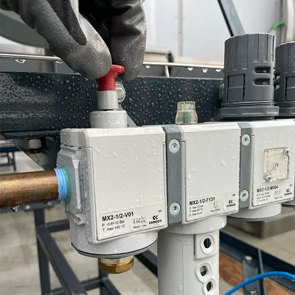
Figure #1
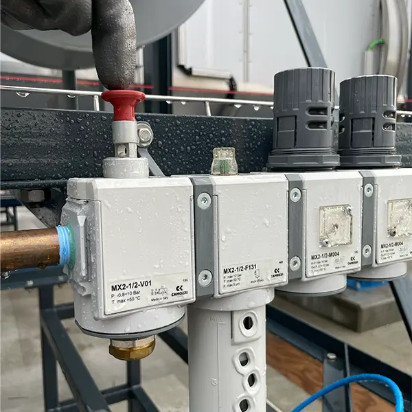
Figure #2
Visual Inspection Automatic Greaser
Maintaining the automatic greaser in optimal condition is a critical aspect of ensuring the efficient operation of the BioDryer. The greaser provides consistent lubrication to the components that facilitate smooth rotation. Without adequate grease, there is a heightened risk of friction and wear, which can lead to significant damage, not only to the moving parts but also to the Polypropylene (PP) pipes connected to the BioDryer reactor body.
Personal Protective Equipment
Timeframe
- Estimated total: 0.25 man hours
Procedure
-
Safety First
- Put on the PPE to protect yourself from any potential hazards.
-
Locate and Remove the old Grease Cartridge
- Find the grease cartridge atop a polypropylene pipe attached to the rear of a BioDryer reactor (Rotation Joint)
- Inspect the level of grease within the cartridge, if the level is below 60ml then continue removing the cartridge by rotating counter clockwise.
- If the current level of fuel is above 60ml then mark the current level and skip steps 2 and 3.
-
Clean Greaser Pipe
- Before replacing the cartridge, clean the greaser threads to ensure no blockages or residue.
- Use cleaning supplies, such as a rag, to wipe around and inside the pipe. Ensure that the pipe is dry and clear of any debris.
-
Replacing Cartridge
- Install the replacement cartridge, Ensure that the new cartridge is secured and properly aligned.
- Rotate the sping mechanism on top of the cartridge to 6 (months).
-
System Activation
- If everything is in order and no additional maintenance is required, the system can be energized and returned to normal operation.
- If Lockout-Tagout (LOTO) is engaged, remove it by turning the main switch on the electrical panel to the "ON" position. Reset the 24v components by pressing the blue reset button until the light goes out.
- Reactivate the BioDryer to normal operational mode using the Human-Machine Interface (HMI).
Water Pump Visual Inspection and Filter Cleaning
Conducting a thorough visual inspection of the water pump, coupled with the opening and meticulous cleaning of the filter located upstream, is a task to ensure efficient discharge of the accumulated condensate. This process also verifies that the water pump is functioning optimally.
Personal Protective Equipment
Timeframe
- Estimated total of 0.50 man hours to complete.
Procedure
-
Safety First
- Put on the PPE to protect yourself from any potential hazards.
-
Visual Inspection of the Water Pump
- Carefully examine the water pump for any visible signs of damage, wear, or irregularities.
- Pay attention to the pump's housing, connections, and any attached components.
- Check for loose hardware on the pump components and mountung brakets.
-
Opening the Filter Housing and Filter Cleaning
- Locate the filter housing that is upstream of the water pump. (See Figure #1)
- Remove the filter element from the housing.
- Clean the filter element thoroughly from any possible sediments.
-
Reassembly
- Place the cleaned filter element back into the filter housing. (See Figure #2)
-
System Activation
- If everything is in order and no additional maintenance is required, the system can be energized and returned to normal operation.
- If Lockout-Tagout (LOTO) is engaged, remove it by turning the main switch on the electrical panel to the "ON" position. Reset the 24v components by pressing the blue reset button until the light goes out.
- Reactivate the BioDryer to normal operational mode using the Human-Machine Interface (HMI).
Figures
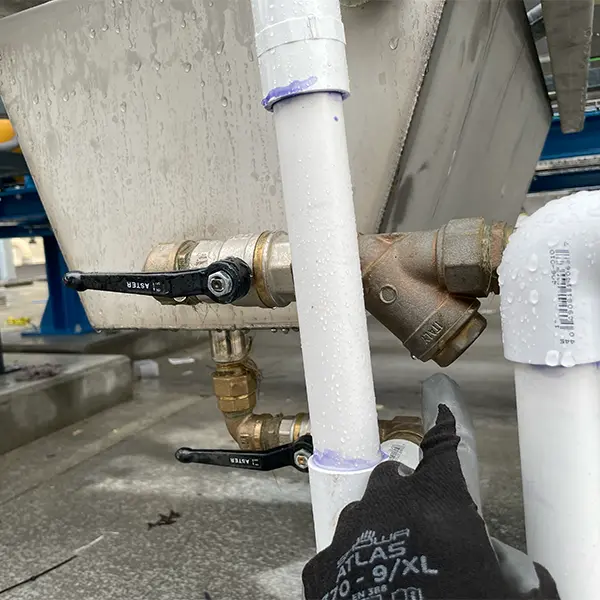
Figure #1
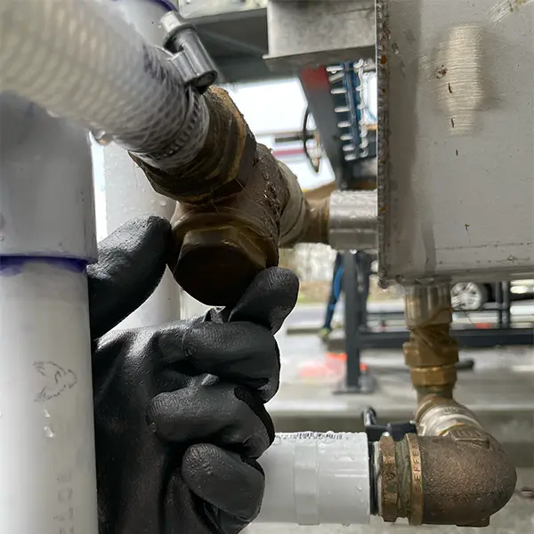
Figure #2
Foul Air Filter Inspection and Cleaning
The foul air filter serves as a crucial protective element, preventing the passage of biosolids granules that might escape the body through the polypropylene piping and potential entrapment within the Air to Air heat exchanger. Positioned between the two components, the filter gradually accumulates material over time. This accumulation poses a risk of obstructing the airflow, ultimately diminishing the BioDryer's efficiency. Regular cleaning of the filter is essential to ensure uninterrupted airflow and maintain optimal BioDryer performance.
Personal Protective Equipment
Timeframe
- Estimated total of 0.50 man hours to complete.
Procedure
-
Safety First
- Put on the PPE to protect yourself from any potential hazards.
-
Locate and Remove the Foul Air Filter
- Locate the Foul Air Filter on the back of the BioDryer between the BioDryer-skid and the Air-Skid. (Filter)
- Remove the locating bolts with a 13mm wrench.
- Remove the Filtering Mesh Frame by pulling away from the cylindrical housing.
-
Washing the Filter
- Move to a safe place and thoroughly wash the filter with a water source.
-
Reassembly
- Place the cleaned filter element back into the cylindrical housing.
- Put the locating bolts back into place and gently tighten.
-
System Activation
- If everything is in order and no additional maintenance is required, the system can be energized and returned to normal operation.
- If Lockout-Tagout (LOTO) is engaged, remove it by turning the main switch on the electrical panel to the "ON" position. Reset the 24v components by pressing the blue reset button until the light goes out.
- Reactivate the BioDryer to normal operational mode using the Human-Machine Interface (HMI).
Pneumatic System Inspection
The Pneumatic System is responsible for opening and shutting various valves and gates on the BioDryer body and Air-Skid. If there is a leak then the proper pressure cannot be maintained and funciton of the BioDryer will halt.
Personal Protective Equipment
Timeframe
- Estimated total of 0.50 man hours to complete.
Procedure
-
Safety First
- Put on the PPE to protect yourself from any potential hazards.
-
Locate the compressed Air Loop
- Start at the Pneumatic air valves located at the utility requirement of Pneumatic Air on the airskid.
- Check the tube for wear or corrosion
-
Follow the tubes
- Follow the various tubes through the Air-Skid, BioDryer, and Loading Screw Conveyor. Ensuring that each connection is secure and no leaks are present along the length.
- One example use of the pneumatic air is to actuate air gates on the BioDryer. (see Figure #2)
- Follow the various tubes through the Air-Skid, BioDryer, and Loading Screw Conveyor. Ensuring that each connection is secure and no leaks are present along the length.
-
Leak Correction
- In the case a leak is present at an interpart connection please re-seat the tube into its slot and listen for leaks. If the problem persists then contact BioForceTech.
- In the event of damage to the tube, contact BioForceTech for a replacement.
-
System Activation
- If everything is in order and no additional maintenance is required, the system can be energized and returned to normal operation.
- If Lockout-Tagout (LOTO) is engaged, remove it by turning the main switch on the electrical panel to the "ON" position. Reset the 24v components by pressing the blue reset button until the light goes out.
- Reactivate the BioDryer to normal operational mode using the Human-Machine Interface (HMI).
Figures:
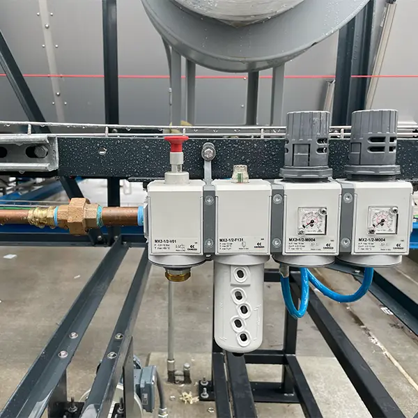
Figure #1
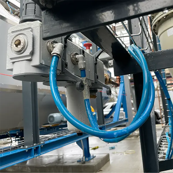
Figure #2