Mechanical Components
BioDryer Skid
An overview of the BioDryer skid and its main components.
Rotating body
The primary structure of the BioDryer features a singular axis of rotation, with an exclusively air-permeable bed designed to facilitate the passage of air through the material undergoing the drying process. This configuration optimizes the exposure of the material to the circulating air mixing it. Five compressed air-actuated gates are used for loading a batch of material into the drying chamber. One of these hatches is also used to empty the chamber when the machine is in the unloading position.
Naming conventions for items:
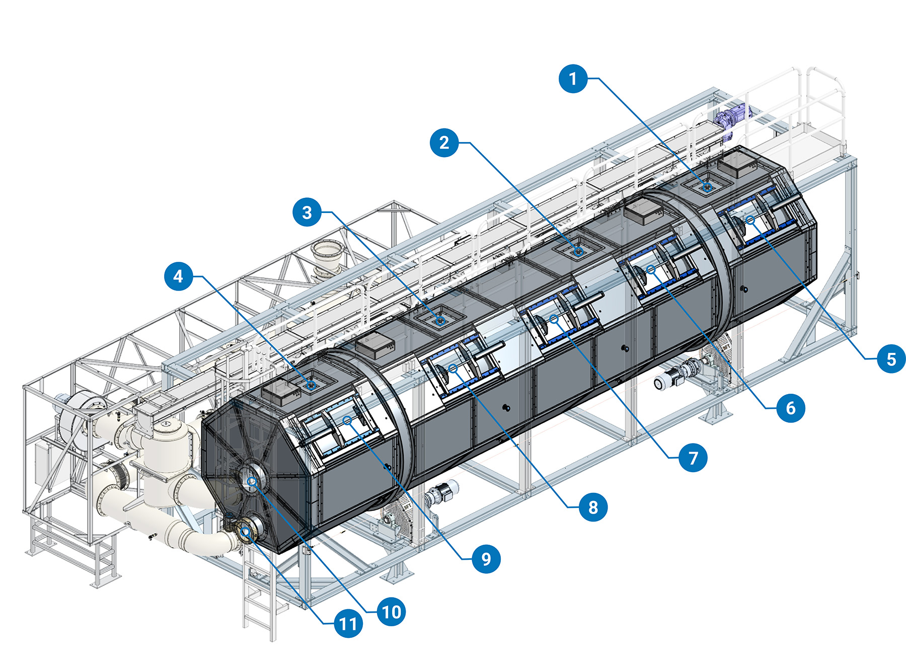
(1)Air Gate N°1 (2)Air Gate N°2 (3)Air Gate N°3 (4)Air Gate N°4 (5)Sludge Gate N°1 (6)Sludge Gate N°2 (7)Sludge Gate N°3 (8)Sludge Gate N°4 (9)Sludge Gate N°5 (10)Rotation Joint (11)Inlet Butterfly Valve
Sludge Gate
The gate is designed to seal the reactor while in process and allow for loading and unloading the biomass. It is powered by a pneumatic cylinder that incorporates a position transducer to monitor accurate gate positioning.
Any Sludge Gates can be used to empty the BioDryer. In its standard configuration is the number one.
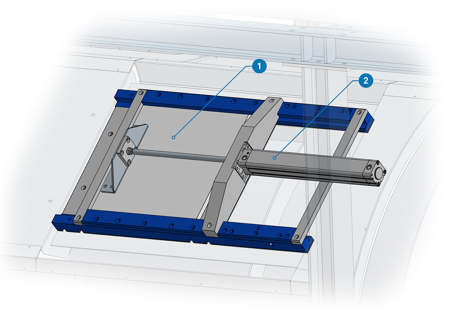
(1)Sludge Gate POM Plate (2)Sludge Gate Pneumatic Cylinder With Transducer
Air Gate
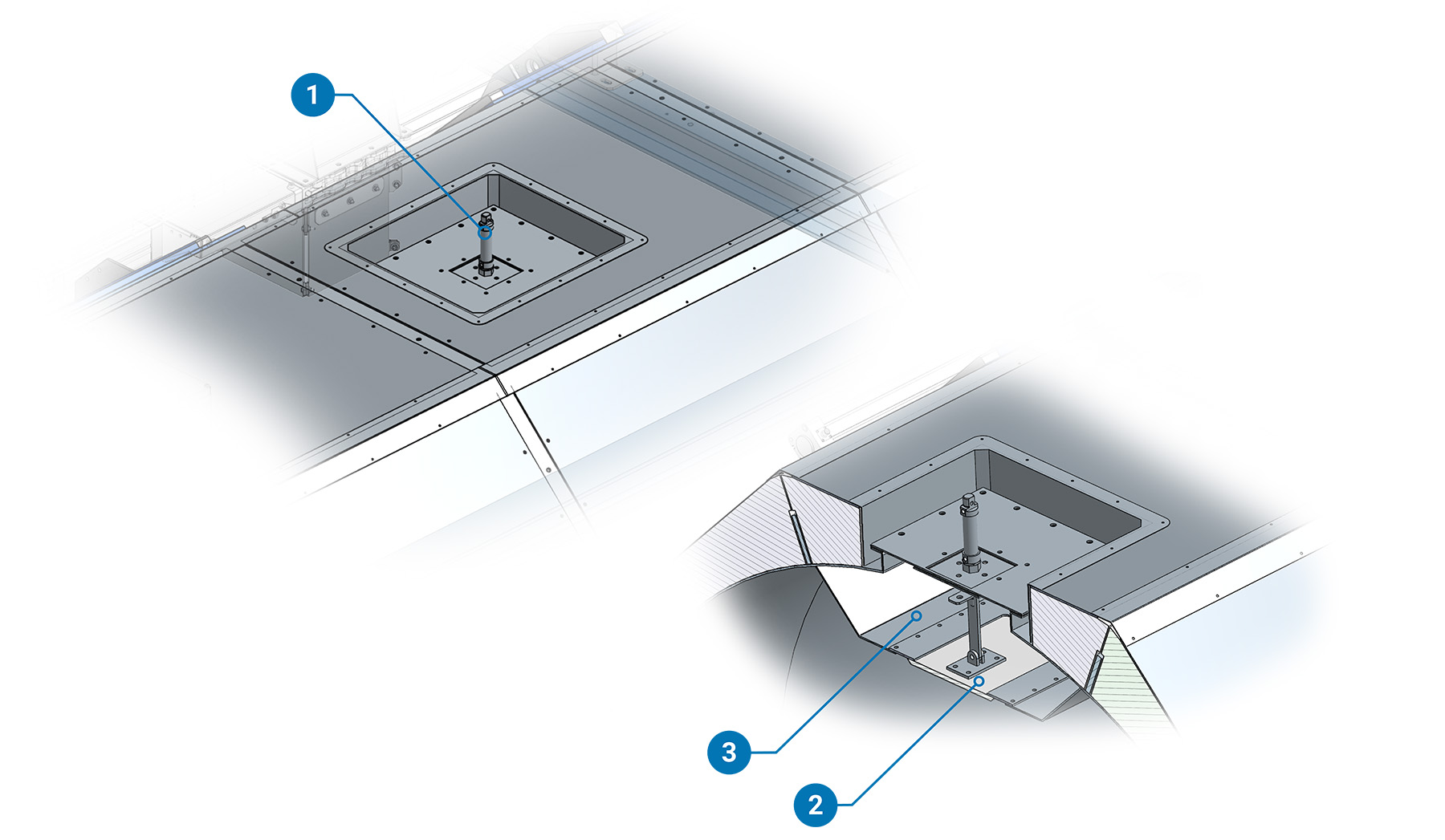
(1)Air Gate Pneumatic Cylinder (2)Air Gate POM Plate (3)Body Air Duct
Rotation Joint
Designed to seamlessly integrate an air pipe that stay stationary while the main body rotates, this joint eliminates the need for disconnection. The seal is guaranteed by a couple of o-rings, complemented by an automatic lubrication system for enhanced durability and performance.
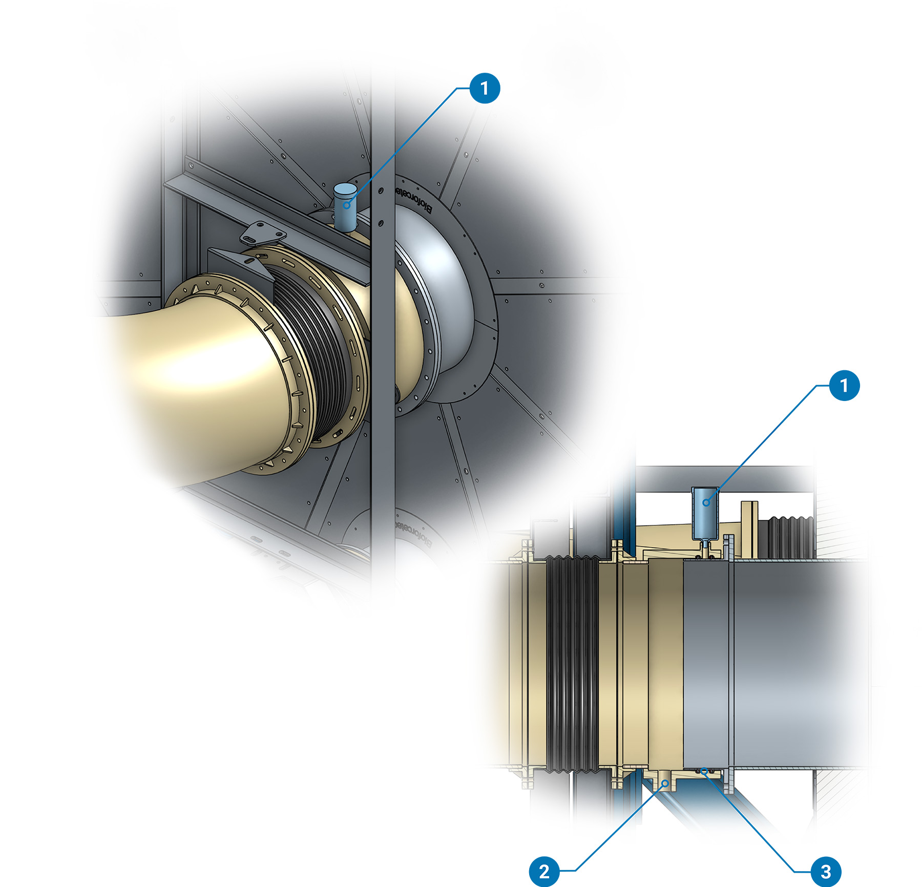
(1)Automatic Lubricant Doser (2)Condensed Water Drain (3)O-Rings Seal
Inlet Butterfly valve
Introducing our butterfly valve, integrated into the BioDryer's rotating body. It include a specialized gasket surface that seals tightly with the moving part of the Air Lock when it engage. This ensures a secure seal during operation, preventing any leakage.
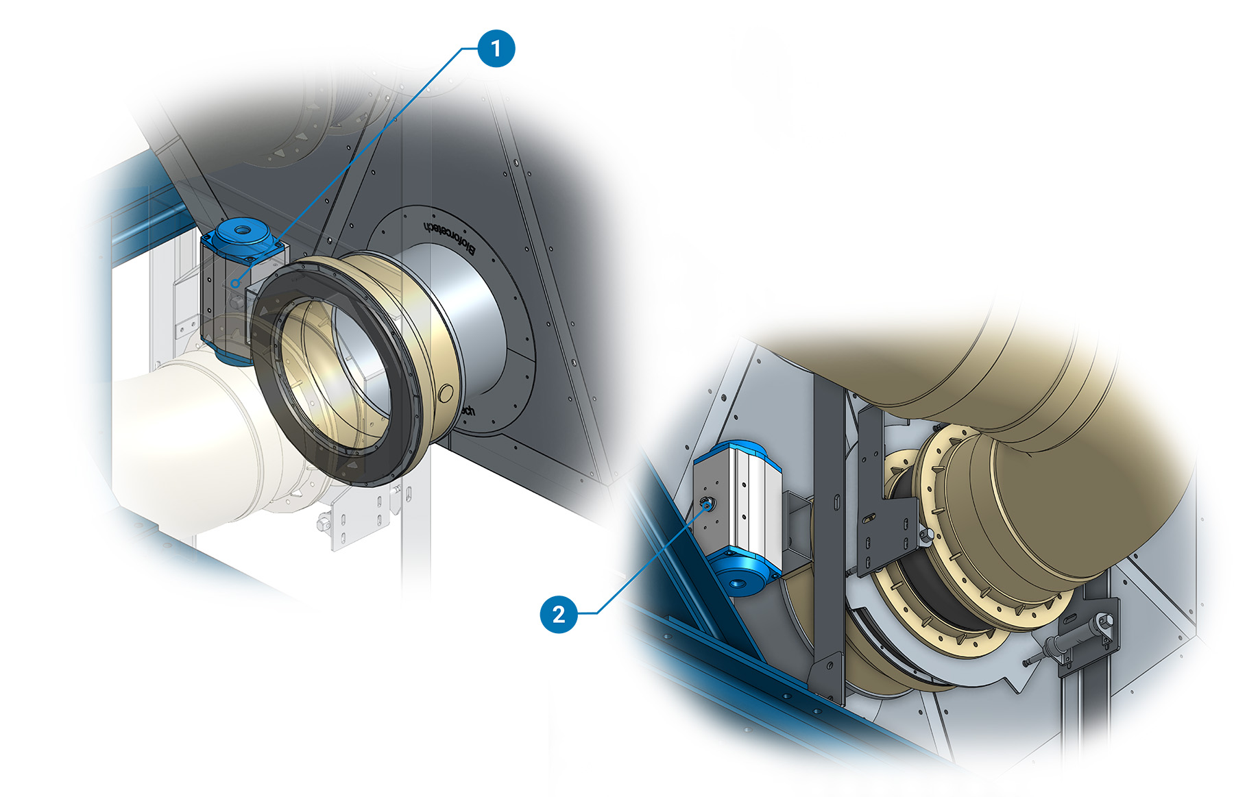
(1)Buttefly Valve Actuator (2)Butterfly Valve Postition Feedback
Main Structure
BioDryer's frame is designed to accommodate a set of four drive wheels, responsible for rotating the main body. Another set of four smaller wheels ensures the alignment of the main body and is structurally designed to facilitate the movement of the entire module.
Naming conventions for items:
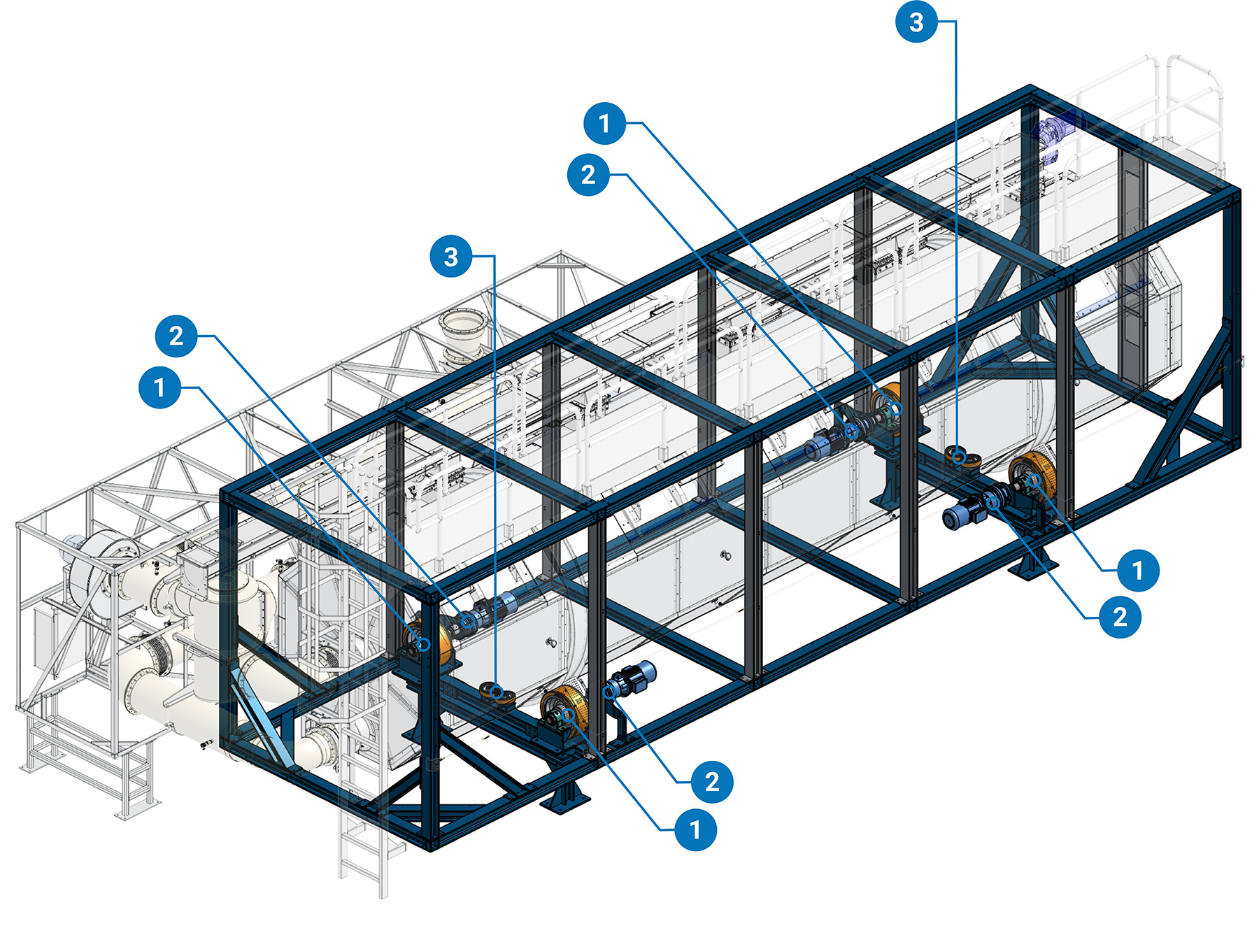
(1)Drive Wheel (2)Gearbox (3)Guide Wheels
Drive Wheels
The motor imparts rotational motion to the wheel, supported by two bearings for stability. The motor is fixed by a torque arm to the main frame.
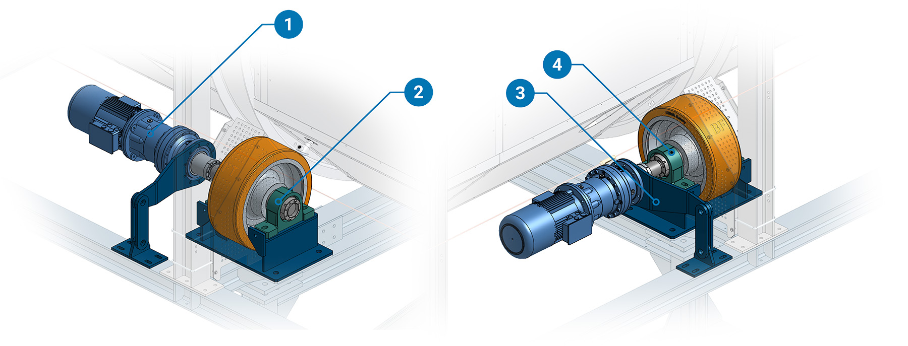
(1)Gearbox (2)Bearing (3)Torque Arm (4)Bearing
Catwalk
The catwalk is designed to allow access to the screw conveyor and perform maintenance on it safely.
Naming conventions for items:
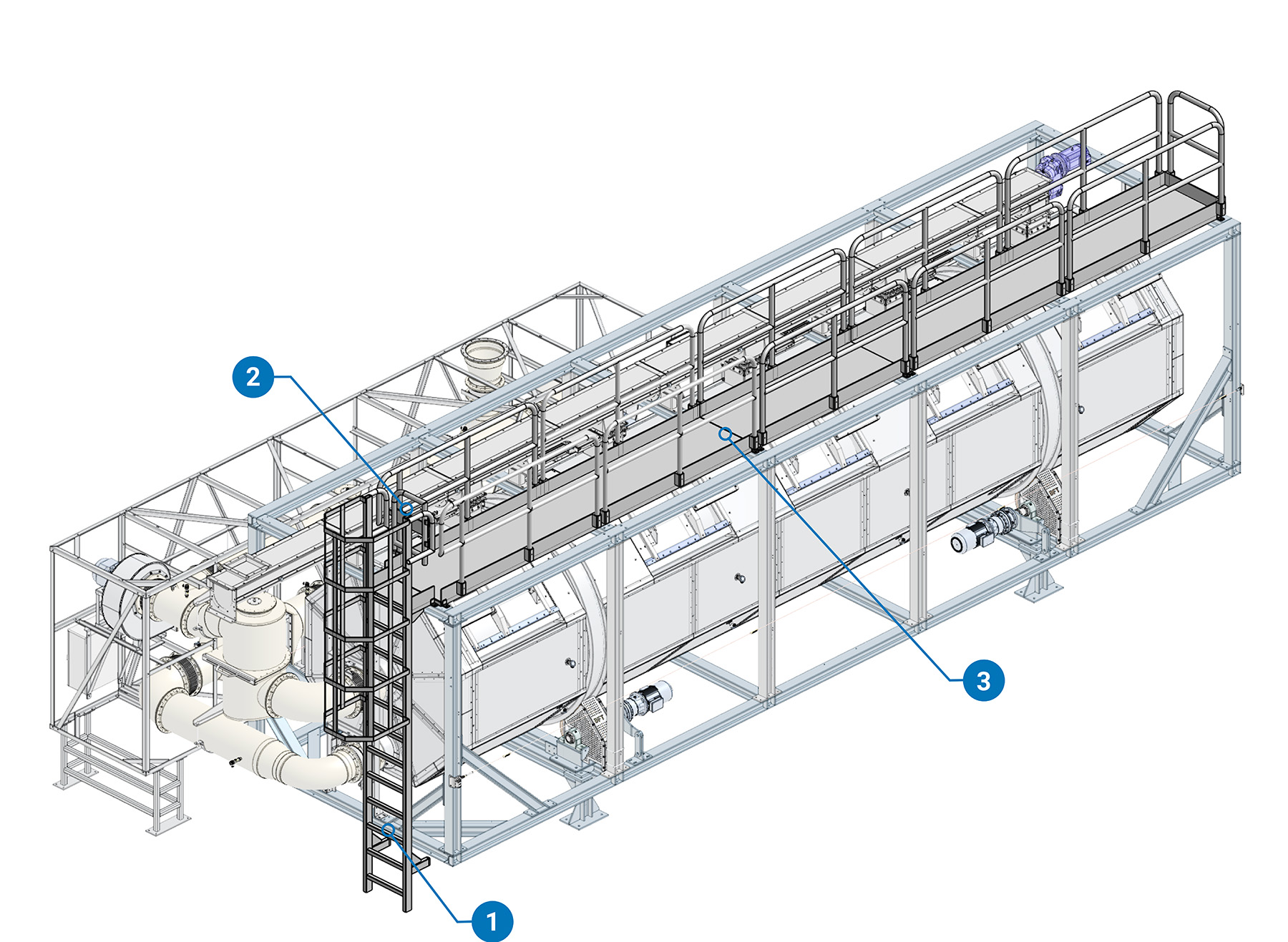
(1)Ladder (2)Gate (3)Walkway
Air Skid
The air skid is the module housing the entire process air management system. It accommodates blowers, heat exchangers and recuperator, their cleaning system along with the condensate collection and the necessary sensors for the machine's operation.
Naming conventions for items:
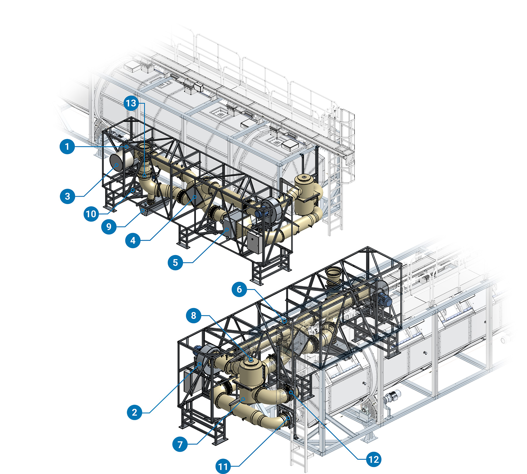
(1)Blower N°1 (2)Blower N°2 (3)Blower Inlet Filter (4)Air-Air Heat Recuperator (5)Water-Air Heat Exchanger (6)Recuperator Washing Nozzle (7)Foul Air Filter (8)Air Filter Washing Nozzle (9)Condensate Tank (10)Condensate Pump (11)Air Lock System (12)Rotation Joint (13)Outlet Butterfly Valve
Air Lock
The Air Lock connection system, driven by three pneumatic cylinders, Seamlessly seal with a gasket or disengage the pipe upon retraction when the BioDryer needs to rotate. The engagement is verified by two proximity sensors.
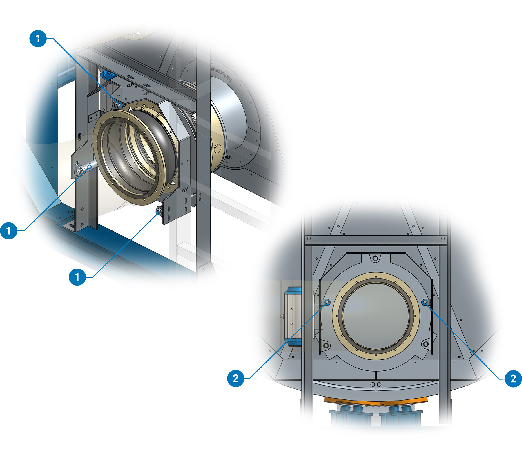
(1)Air Lock Pneumatic Cylinder (2)Air Lock Position Proximity
Foul Air Filter
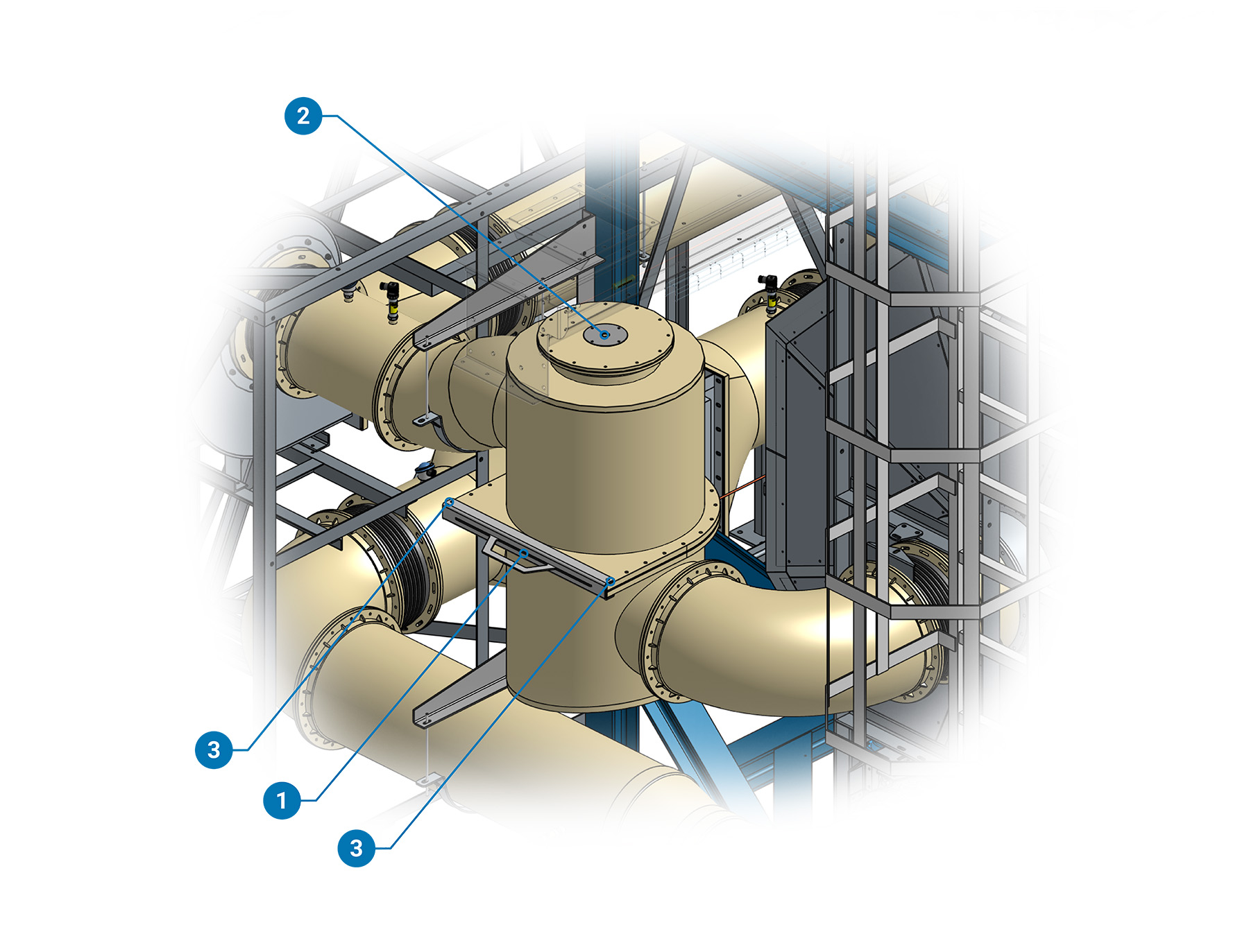
(1)Filtering Mesh Frame (2)Washing Nozzle Connection (3)Filtering Mesh Pins
Screw Conveyor
The screw conveyor is specifically designed to uniformly load the main body throught the Sludge Gates, ensuring an efficient process.
Naming conventions for items:
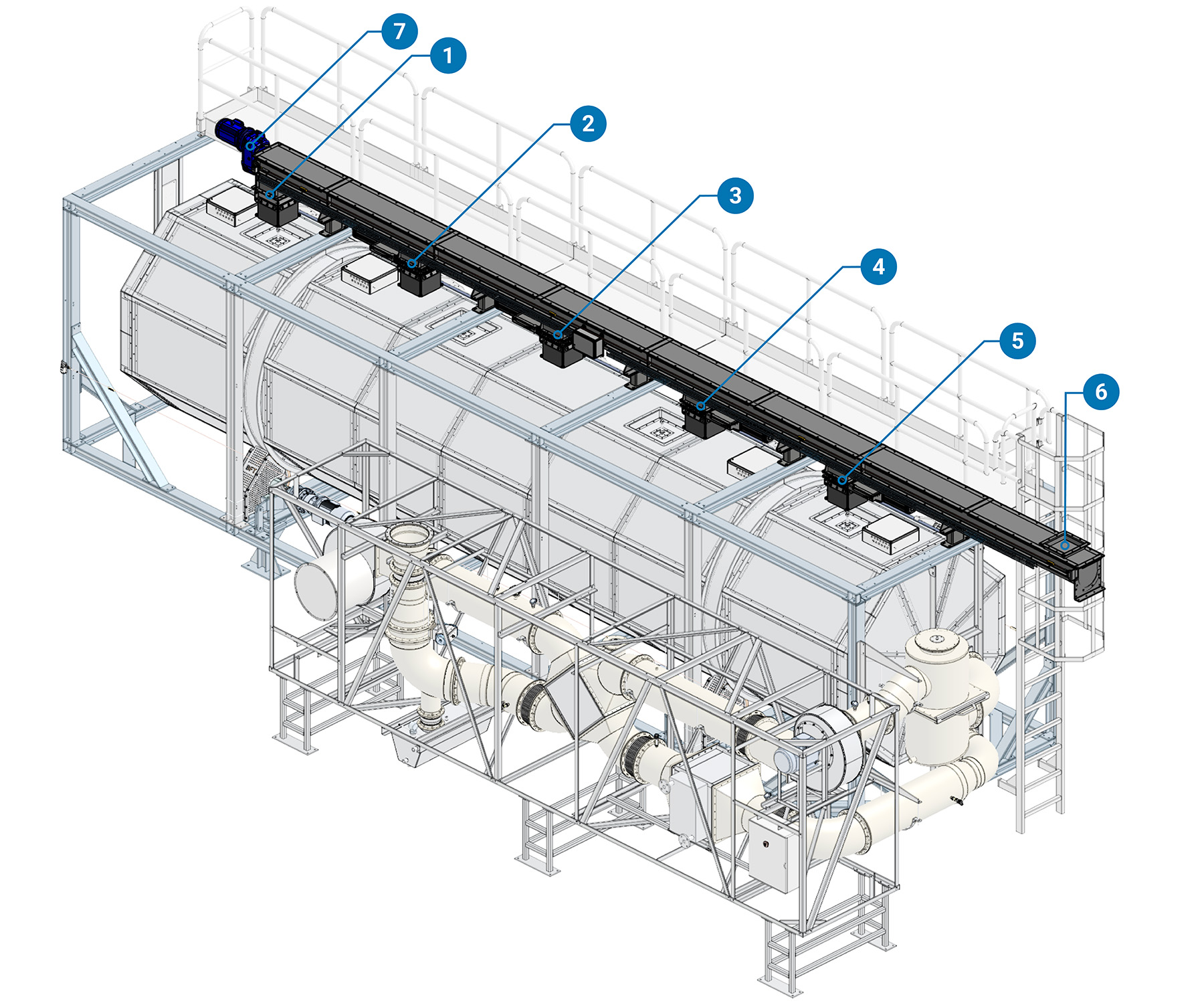
(1)Screw Gate N°1 (2)Screw Gate N°2 (3)Screw Gate N°3 (4)Screw Gate N°4 (5)Screw Gate N°5 (6)Inlet Chute (7)Screw Gear Box