Sensors & Actuators
Here we'll show roles and positions for each sensor and actuator within the system.
Index List
Below is a comprehensive list of all the different sensors utilized for monitoring and operating the BioDryer.
| Description | Type | Section | Quantity |
|---|---|---|---|
| Sludge Temperature High | Analog Input | Rotating Body | 4 |
| Sludge Temperature Low | Analog Input | Rotating Body | 4 |
| Sludge Gate Position | Analog Input | Rotating Body | 5 |
| Sludge Gate Pneumatic Valve | Digital Output | Rotating Body | 5 |
| Air Gate Pneumatic Valve | Digital Output | Rotating Body | 4 |
| Air Gate Position Detection System | Digital/Analog Input | Rotating Body | 8/4 |
| Inlet Butterfly Valve | Digital Input | Rotating Body | 1 |
| Inlet Butterfly Pneumatic Valve | Digital Output | Rotating Body | 1 |
| Encoder | Digital Input | Rotating Body | 1 |
| Body Compress Air Sensor | Digital Input | Rotating Body | 1 |
| Rotation Position Proximity | Digital Input | BioDryer Skid | 2 |
| Load Cell | Analog Input | BioDryer Skid | 4 |
| Air Skid Compress Air Sensor | Digital Input | Air Skid | 1 |
| Outlet Butterfly Valve | Digital Input | Air Skid | 1 |
| Outlet Butterfly Pneumatic Valve | Digital Output | Air Skid | 1 |
| Air Temperature | Analog Input | Air Skid | 5 |
| Air Pressure | Analog Input | Air Skid | 4 |
| Air Lock Position | Analog Input | Air Skid | 2 |
| Air Lock Pneumatic Valve | Digital Output | Air Skid | 1 |
| Air Velocity | Analog Input | Air Skid | 1 |
| Water Level Tank | Digital Input | Air Skid | 1 |
| Wash Cycle Pneumatic Valve | Digital Output | Air Skid | 2 |
| Screw Gate Proximity | Digital Input | Screw Conveyor | 8 |
| Screw Gate Pneumatic Valve | Digital output | Screw Conveyor | 4 |
| Screw Zero Switch | Digital Input | Screw Conveyor | 1 |
Rotating Body
An overview of all the sensors and actuators to monitoring the BioDryer.
Sludge Temperature
This set of thermocouples is deployed on the Rotating Body to monitor the sludge temperature in different zones and layers inside the BioDryer.
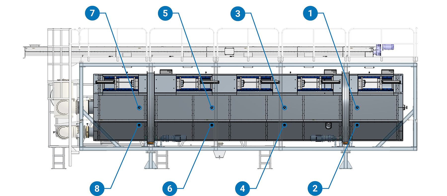
(1)Sludge Temperature High N°1 (2)Sludge Temperature Low N°1 (3)Sludge Temperature High N°2 (4)Sludge Temperature Low N°2 (5)Sludge Temperature High N°3 (6)Sludge Temperature Low N°3 (7)Sludge Temperature High N°4 (8)Sludge Temperature Low N°4
Sludge Gates
Operated by a pneumatic cylinder that incorporates a transducer for monitoring the piston position. This setup enables precise control over actuation timing.
Four set of double or triple manifold, located near to the Juction Boxes on the Rotating Body, one of the valve will be respondable for the cylinder actuation.
Check on the electrical schematics of your machine for more details about every Air Lock and its relative control valve.
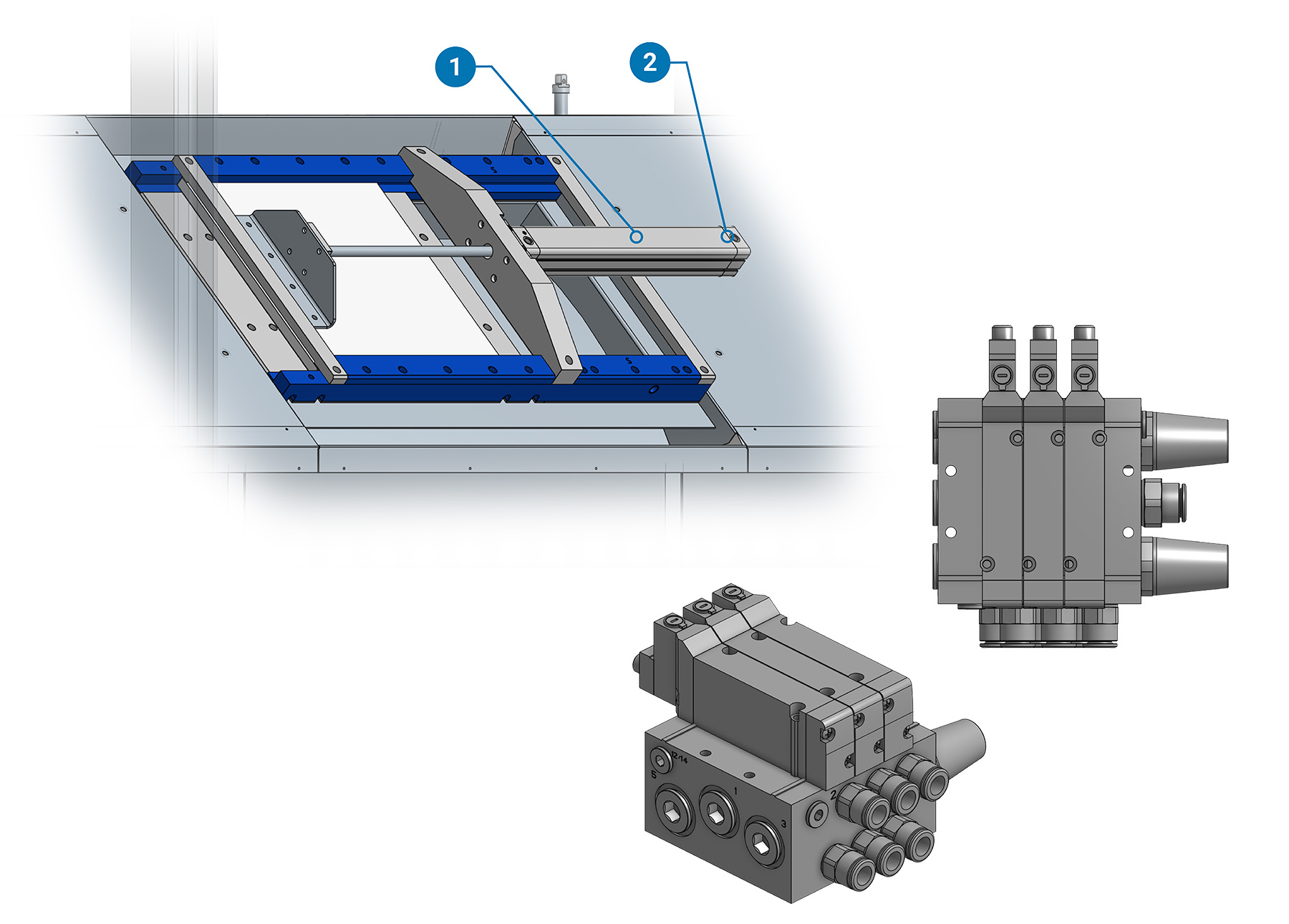
(1)Sludge Gate Pneumatic Cylinder (2)Sludge Gate Pneumatic Cylinder Transducer
Air Gates
System A: Digital Proximity pair
A pair of proximity sensors ensures precise feedback regarding the position of a pneumatic cylinder. Both proximity sensors ensure the closed position of the Air Gate. It is essential that those are close during rotation.
System B: Analog Transducer
A transducer ensures precise feedback regarding the position of a pneumatic cylinder. The sensors ensure the closed position of the Air Gate. It is essential that those are close during rotation.
Four set of double or triple manifold, located near to the Juction Boxes on the Rotating Body, one of the valve will be respondable for the cylinder actuation.
Check on the electrical schematics of your machine for more details about every Air Lock and its relative control valve and which type of positioning feedback system has been installed on your BioDryer.
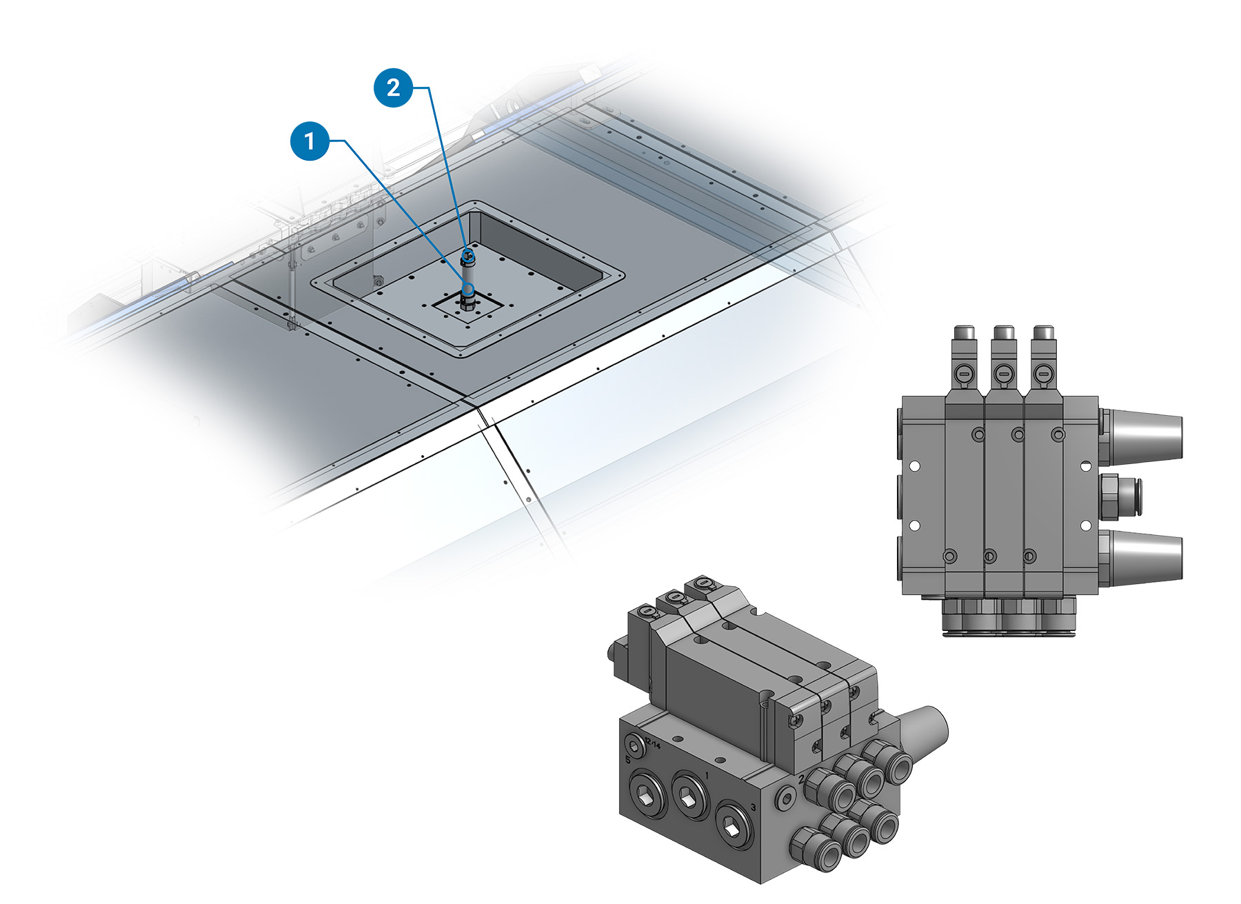
(1)Air Gate Pneumatic Cylinder (2)Air Gate Digital Proximity Pair/Air Gate Analog Transducer
Check on the electrical schematics of your machine for more details
Inlet Butterfly Valve
The butterfly valve actuator features a control valve attached to its side and a position sensor mounted on top of the actuator body.
The relative control valve could be found mounted on an angle of the inner frame of the Air Skid. Please look at the label. Position may vary.
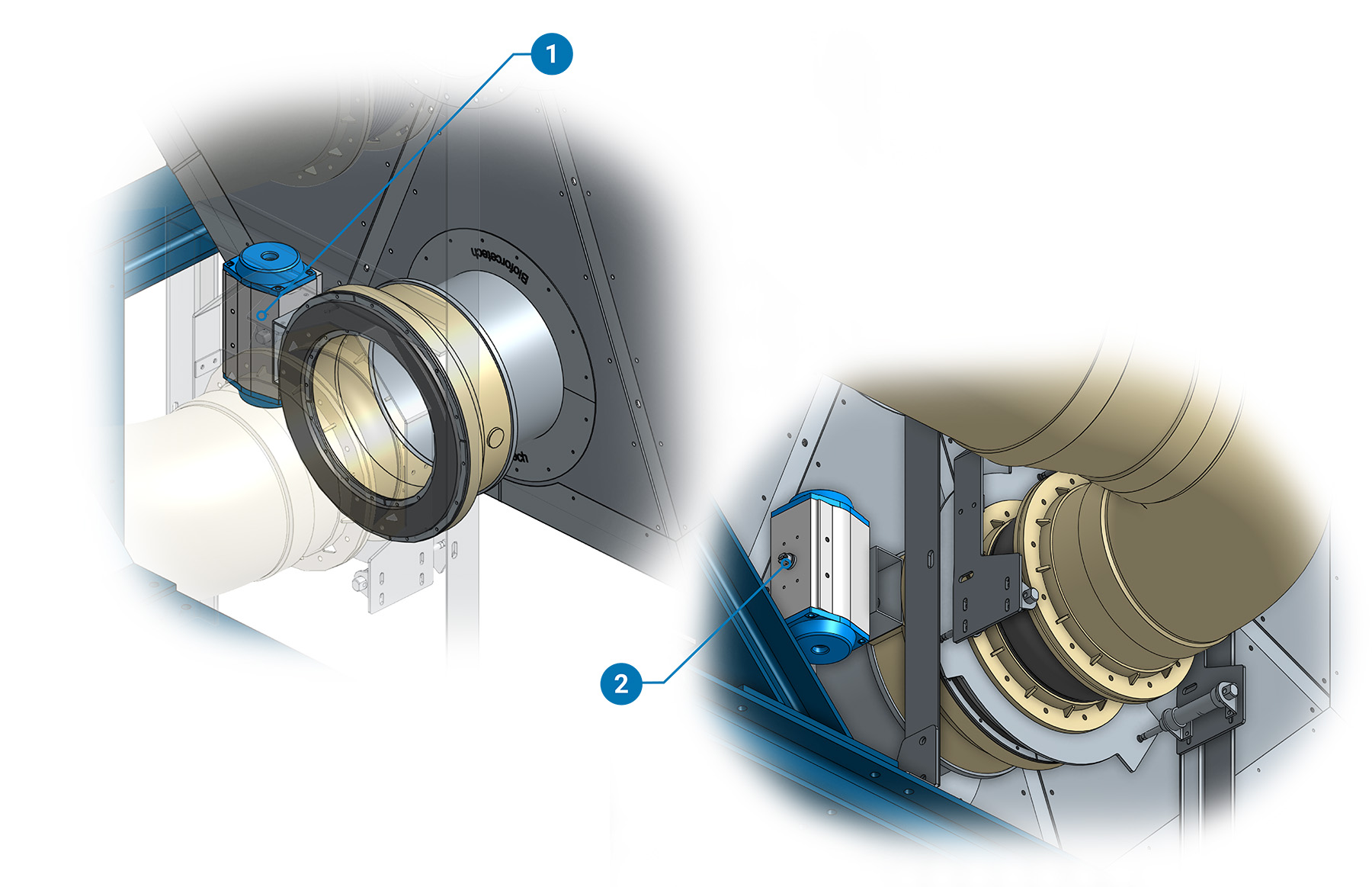
(1)Inlet Buttefly Actuator (2)Inlet Butterfly Position Sensor
Encoder
An encoder is mounted to monitoring the relative position between the Rotating Body and the Main Skid. It provides continuous feedback, enabling the precise determination of the rotating body's position at any given moment.
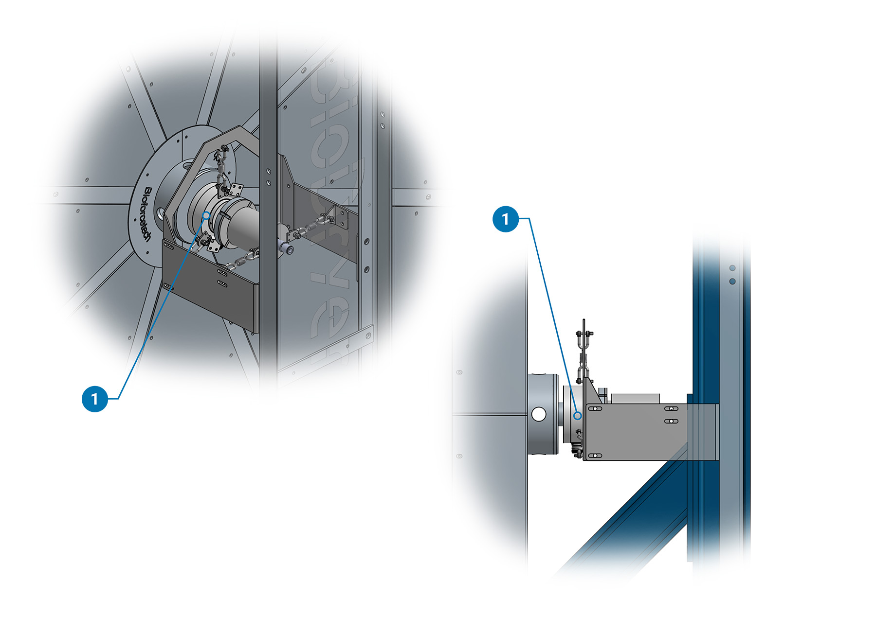
(1)Encoder
The frame elements that fix in position encoders stationary part may very depending on the specific BioDryer. Refer to the technical drawings for more details if needed.
Body Compress Air Sensor
A pressure sensor is used to monitor pressure within a compressed air system.
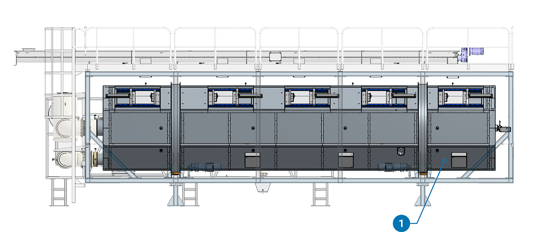
(1)Compress Air Pressure Sensor
The mount posistion may vary dependig on the BioDryer Version.
BioDryer Skid
Rotation Position Proximity
A system comprising a pair of proximity sensors, along with four targets on a rotating body, is designed to precisely determine its position. By detecting combinations of targets in three delineated positions (0-1, 1-0, 1-1), the sensors ensure accurate feedback regarding the rotation body's orientation as a double check for the Encoder reading.
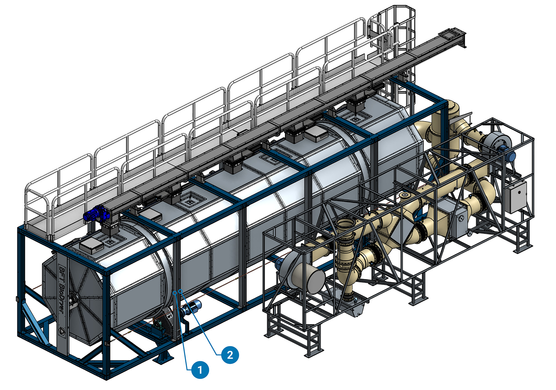
(1)Position Check Proximity N°1 (2)Position Check Proximity N°2
The position of this system, comprising the pair of proximity sensors and the four targets on the rotating body, remains consistent regardless of the biodryer configuration. The main body remains unchanged.
Load Cells
A set of four load cells is positioned between the main biodryer skid and its legs to weigh the material inside and assess its balance.
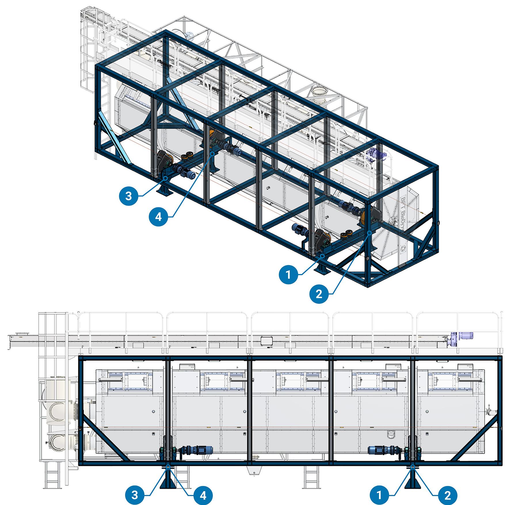
(1)Load Cell N°1 (2)Load Cell N°2 (3)Load Cell N°3 (4)Load Cell N°4
Air Skid
An overview of all the sensors and actuators to monitoring the air flow on the Air Skid.
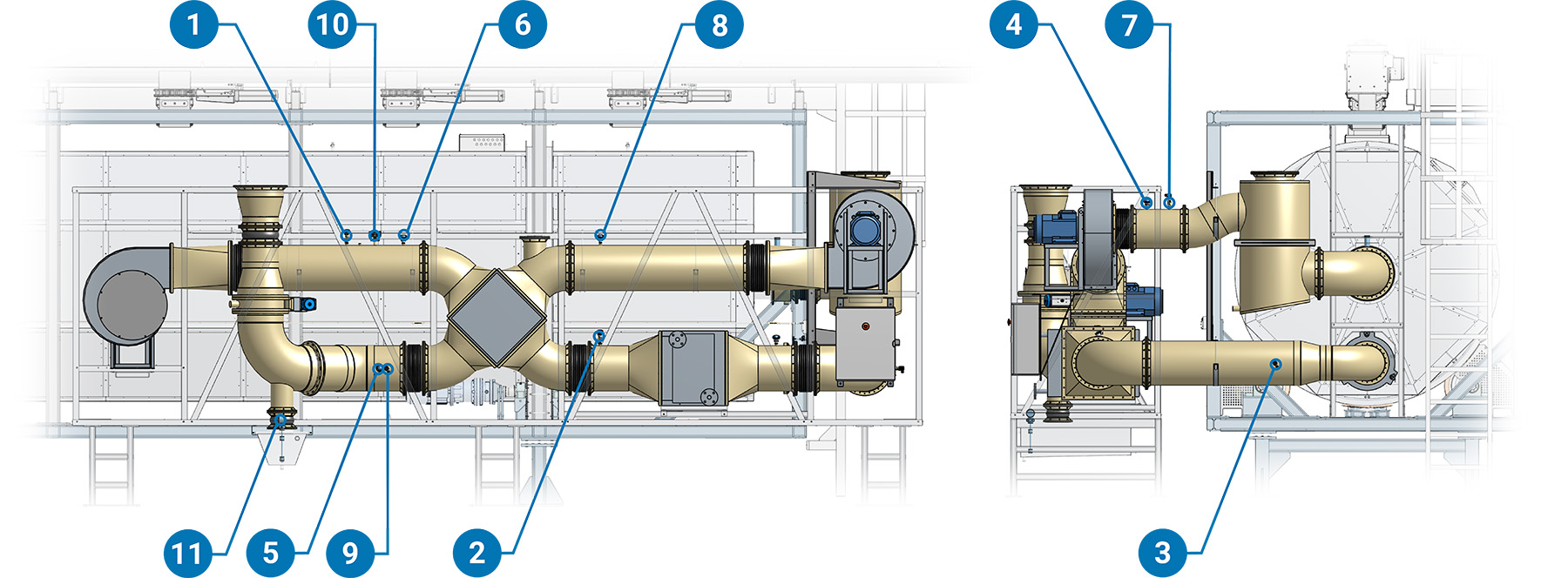
(1)Air Thermocouple N°1 (2)Air Thermocouple N°2 (3)Air Thermocouple N°3 (4)Air Thermocouple N°4 (5)Air Thermocouple N°5 (6)Air Pressure N°1 (7)Air Pressure N°2 (8)Air Pressure N°3 (9)Air Pressure N°4 (10)Air Velocity (11)Condensate Water Tank Levels
Air Lock
The Air Lock connection system, driven by three pneumatic cylinders, Seamlessly seal with a gasket or disengage the pipe upon retraction when the BioDryer needs to rotate. The engagement is verified by two proximity sensors.
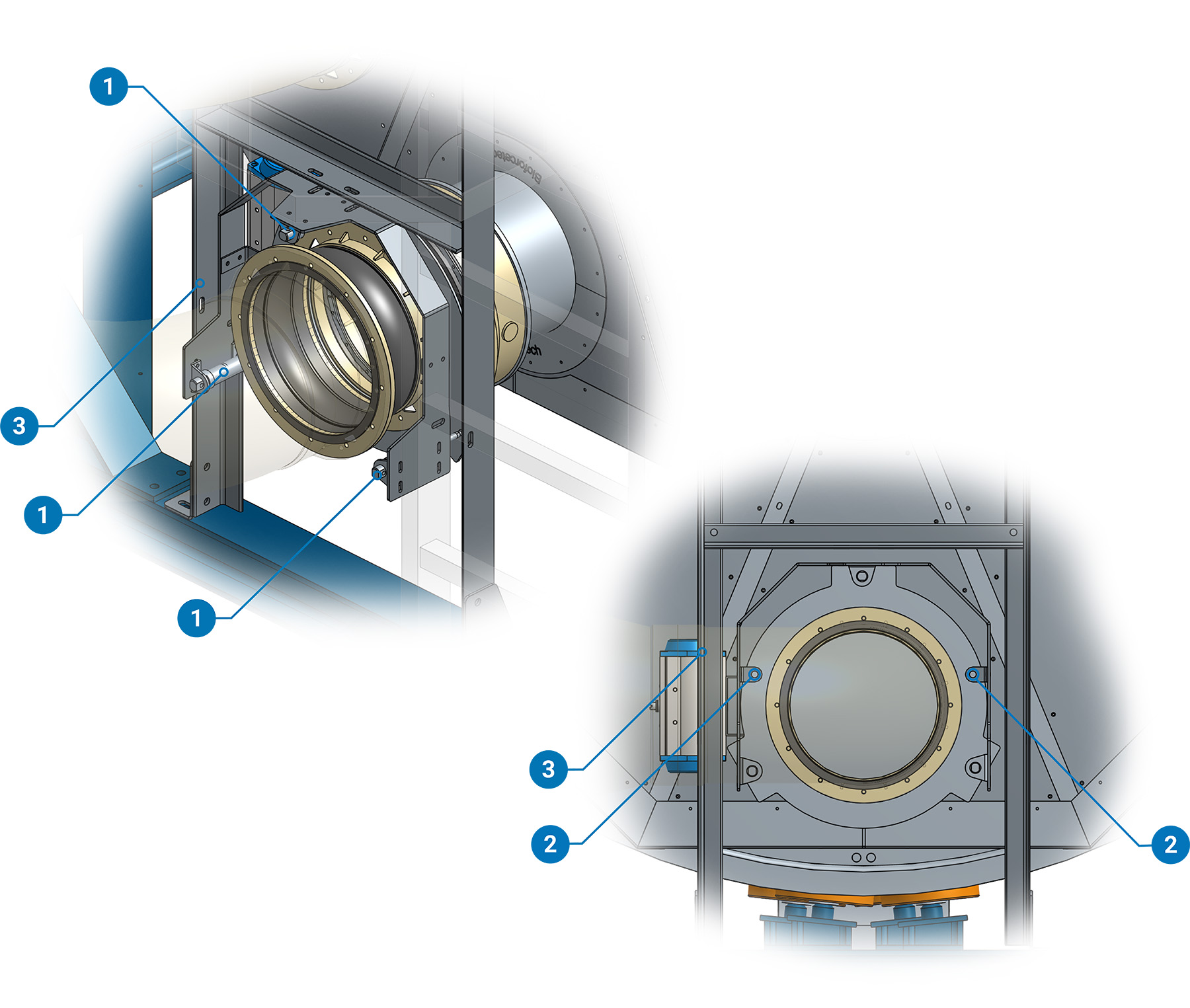
(1)Air Lock Pneumatic Cylinder (2)Air Lock Position feedback (3)Control Valve Mounting Position
Outlet Butterfly Valve
A butterfly valve with pneumatic actuation is placed to isolate the BioDryer piping when it's not processing. that way the filtration blower does not suck in air from the open Air Lock.
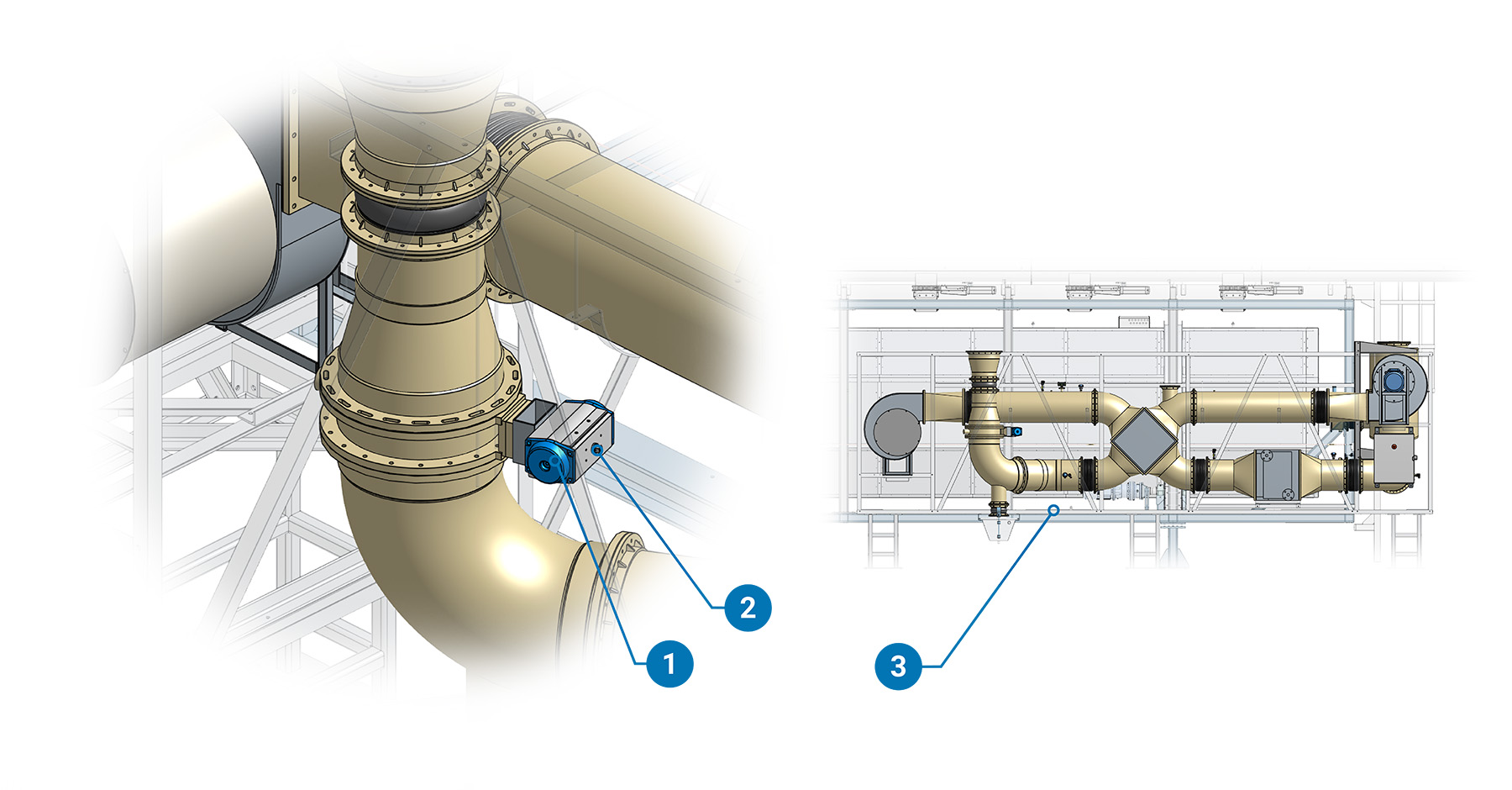
(1)Outlet Butterfly Valve Acturator (2)Valve Acturator Position Sensor (3)Control Valve Mounting Position
The relative control valve could be found mounted on an angle of the bottom frame of the Air Skid. Please look at the label. Position may vary.
Air Skid Compress Air Sensor
A pressure sensor is used to monitor pressure within a compressed air system.
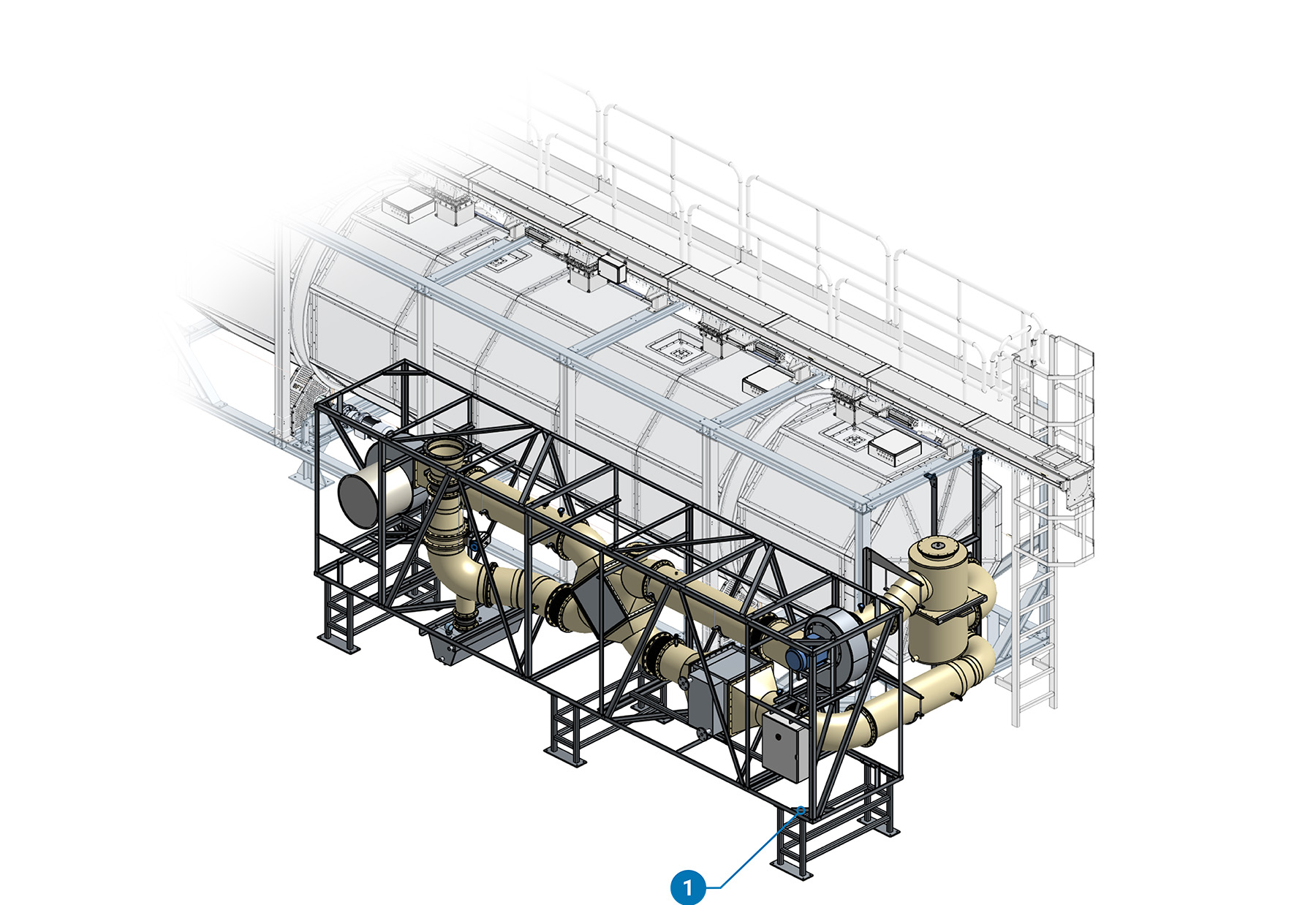
(1)Compress Air Pressure Sensor
The mount posistion may vary dependig on the BioDryer Version.
Air Skid Washing Valves
A pair of pneumatic valves actuates a set of ball valves to initiate the washing cycles for the heat exchanger and the filter.
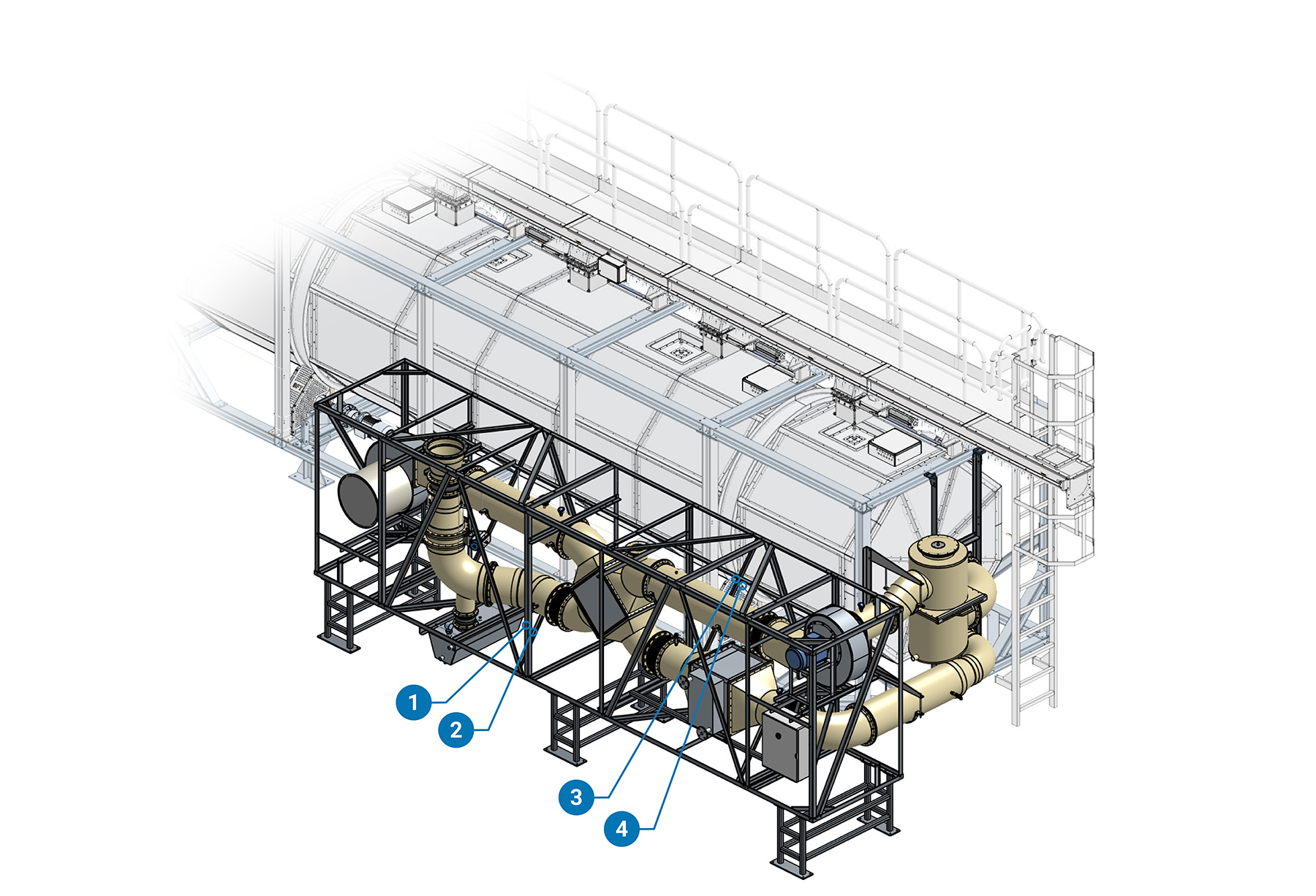
(1)Ball Valve for air heat recuperator wash (2)Ball Valve for filter wash (3)Pneumatic Valve for air heat recuperator wash (4)Pneumatic Valve for filter wash
Screw Conveyor
Pneumatic valves, actuators and sensors that control screw conveyors operation.
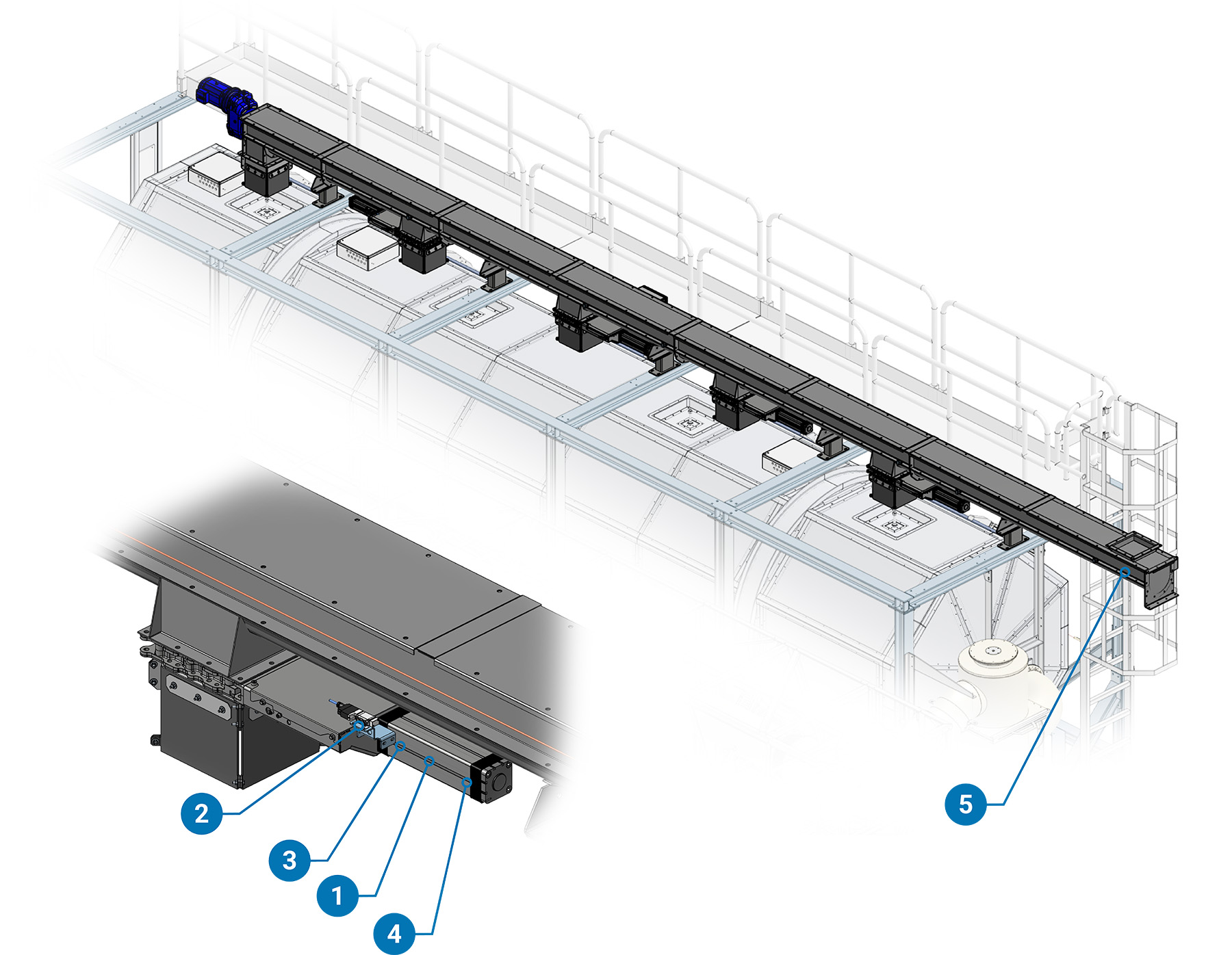
(1)Screw Gate Pneumatic Cylinder (2)Screw Gate Control Valve (3)Screw Gate Position Proximity 1 (4)Screw Gate Position Proximity 2 (5)Screw Conveyor Zero Switch